Saturday, August 14, 2021

Truck overhaul 01

 Alright, buckle in, this is a long one, but I've put a lot of work into this truck, so here goes.

I got a 1986 F150 back in college for $800. RWD and computer controlled carburetor. It's currently 4x4 with an aftermarket throttle body fuel injection system. Here are some photos from the engine swap.

 First, a photo of my truck (left) and the donor vehicle (right). The donor vehicle was a 1989 4.9 4x4 F-150 with a frame that had snapped/rusted in half and gremlins in the electricals. 

 
Pulling the front clip to get to the engine bay
 
1989 F-150 engine bay. Even '89 is too complicated in my opinion. My truck engine bay is much less cluttered.
 
Engine out! (Yes, I know, rigging could be better)
Also if you look closely, the engine holds a surprising amount of coolant that drains when it's tipped forward...
 
Cleaning up the new engine before installation on a HarborFreight stand I don't trust...
 
Uh, that's quite the warning about something that should be pretty innocuous... I guess I should make sure I don't overheat any of my seals...
 

Better rigging the second time.
 
Old engine out!


Rolled the truck outside to do some powerwashing. You know when you're washing a spoon under a faucet, and turn it the wrong way, and it soaks you? Imagine your faucet is a 5hp powerwasher, and your spoon is a grease/oil coated transmission bell housing... I looked like I had been in a mudslinging contest. No photos of that haha, though the truck did clean up pretty nicely.

Coating the frame and crossmembers with rust converter/protector while it's easily accessible.

Makes it look better too, look at that shiny black.

New engine going in!

If you get the chance, having the option to work outdoors is pretty great.

Alright, now the engine is in, time to make it run. The old system used a low pressure fuel pump for the carburetor, but the new fuel injection system needs a high pressure fuel pump (at least 60psi). The distributor has to be aligned/timed so the spark plugs fire at the right time. The intake and exhaust manifolds also need to be mounted, and there's some wiring to do.

Pretty clean wiring splice job if I do say so myself.

First issue... 2 of the three bolts (around the manifold opening in the photo above) holding the exhaust manifold to the intake manifold were rusted in, and snapped off. I took the manifold down to one of the local shops, and they tried to weld to the bolts to remove them, but the welds snapped, so they would have needed to be drilled out, and the manifold re-tapped with threads for the new bolts. At that point I figured one bolt was plenty strong enough, and the worst it would be likely to do is leak a little. Turned out I was right, and it's been running that way ever since. At some point I'm going to change exhaust manifolds to a later design to get more power out of the engine, at which point it won't be an issue since they don't have the same bolt setup there.

Test fitting. Surprisingly hard to line up, not destroy the gasket, and tighten the bolts to hold it in place all at the same time. It's only probably 25 lbs, but the hoist helps, especially since it's at an awkward angle.

Intake and exhaust manifolds in and mounted.

Square bore/4 barrel to 2 barrel carburetor adapter and gasket installed.
 
EFI unit mounted (still needs some hookup)

And we've got fuel and throttle and wiring :) 

High pressure EFI line is surprisingly expensive. I paid about $200 for 2 spools of hose (more than I needed, but the shop was closing early, I didn't want to have to find some other place, and I figure I'll use it on some other project eventually anyway. If I'd measured carefully I probably could have kept that under $100, but now I've got spare hose, which is good because I want to convert it to a single pump setup. (That's a different topic though)

There's more to come too. I'll probably do another post at some point about the 4x4 drivetrain swap, and then more of the future upgrades I have planned as well. (I have locking differentials, and an engine rebuild/swap is in the works) I'm hoping to turn this into a prerunner for desert racing sort of stuff, but still keep it usable as a work truck. Should be fun and a bit unique.

Wednesday, January 29, 2020

General update

A lot has happened since the last post, hopefully I'll be posting on here more in the future. Major happenings:

  • I graduated college and got a job
     
  • My senior design project won the The Outstanding ECE Senior Design Project Award. (Somewhat related to the previous post)
     
  • I did a major portion of the electronics design and construction for the Rocketry Club at GMU Battle of the Rockets entries in 2018 and 2019 (sounding rocket and mars rover) Turned out pretty well. http://www.rocketbattle.org/winners.html
     
  • I did an engine swap and a lot of upgrades to my truck, got much better at automotive work, and learned quite a bit in the process.

 I'll probably be posting quite a bit about the truck modifications as I've spent the past month working on it, and it's pretty neat.
All for now, hopefully more soon.

Wednesday, January 30, 2019

DSP setup


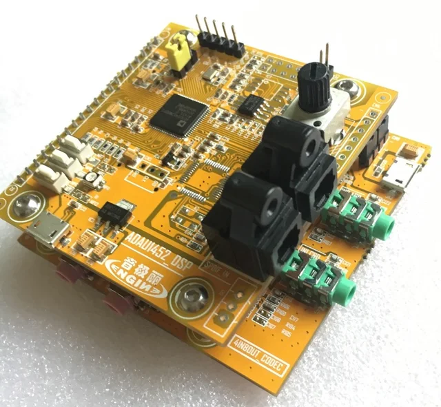
Recently I got a DSP development board off ebay for ~$60. It uses the Analog Devices ADAU1452 chip, and comes with a 4x8 I/O board based on the codec. I had difficulty finding documentation for setting it up, so here's my walkthrough on the setup process. However, if you don't have more time than money, just buy the complete kit from Analog Devices, it's not that much more expensive.

1. Get a board. They typically run about $60 or so, and can usually be found on ebay or aliexpress. They look like this:
https://ae01.alicdn.com/kf/HTB16bI_oNGYBuNjy0Fnq6x5lpXap/ADAU1452-DSP-development-board-learning-board-DSP-board-CODEC.jpg_640x640.jpg

2. Get a programmer. I was hoping not to need this part when I ordered my board, given that the development board has a USB port on it, but it turns out that unpopulated chip in the photo above would be needed for that. This is the programmer I used: https://www.tindie.com/products/maxtch/sigmalink-usbi/. It's less than half as expensive as the official one, and so far has done everything I need. There appear to be a number of USBi adapters on ebay and aliexpress as well.


SigmaLink USBi 1
https://docs.google.com/document/d/13BDac6Mss2I0CBOsSrk4YG-c8GQUpgU41vkwsMnYBss/edit#

3. Wire it up. If using the I2C mode (which I am) you only need three wires: SDA, SCL, and GND. I'd recommend getting a set of jumpers like these if you don't already have some: smile.amazon.com/EDGELEC-Breadboard-Optional-Assorted-Multicolored/dp/B07GD2BWPY
On my board, working left to right as oriented in the first picture, the pins are labelled:
1: GND
2: MOSI
3: SDA / MISO
4: SS
5: SCL / SCLK

On the USBi the pins are as follows. The view is facing the pins on the USBi, notch on the left.


Wiring is very simple, connect GND to GND, SDA to SDA, and SCL to SCL. At this point everything should be ready to go.

4. Program it. I used Sigmastudio 4.2 (the latest version at time of writing)
Opening sigmastudio you should see this:

 Create a new project, and from the toolbox on the left, drag and drop the USBi module and the ADAU1452 module into the main workspace. The USBi module should have a green status bar. If it does not, the program cannot detect the USBi. If you have issues, try a different USB port, and/or rebooting. On my laptop it works anywhere except one specific USB port, but that USB port works for everything else, so that's a bit odd.
Connect the USBi module to the ADAU1452 module. I used the first slot, but it shouldn't matter which one you select. SigmaStudio defaults to SPI communication, but I'm using I2C, so I need to modify the mode. My board used I2C address 0x76 (118). It should look like this (except with a green status bar instead of red):


Now we can check communication. Click on the IC 1 ADAU145x Register Controls tab right next to the current config tab (bottom left of the middle window) That will bring you to a set of register control and status tabs. Scroll down (or don't if you have a better screen than I do) and click read all registers. You should see all the parameters being read scroll past on the capture screen at the bottom of the window.


If it didn't throw an error, and you were able to read the data, you've got connection! Now all you need to do is go to the schematic tab at the top and build your program. I may do some test design walkthroughs at a future date, but there are plenty of examples elsewhere online.