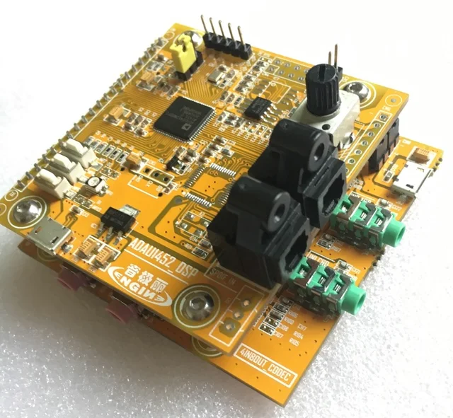
Recently I got a DSP development board off ebay for ~$60. It uses the Analog Devices ADAU1452 chip, and comes with a 4x8 I/O board based on the
1. Get a board. They typically run about $60 or so, and can usually be found on ebay or aliexpress. They look like this:
 |
/i/19843/products/2018-04-26T05%3A10%3A59.048Z-DSCN0003.JPG) |
| https://docs.google.com/document/d/13BDac6Mss2I0CBOsSrk4YG-c8GQUpgU41vkwsMnYBss/edit# |
3. Wire it up. If using the I2C mode (which I am) you only need three wires: SDA, SCL, and GND. I'd recommend getting a set of jumpers like these if you don't already have some: smile.amazon.com/EDGELEC-Breadboard-Optional-Assorted-Multicolored/dp/B07GD2BWPY
On my board, working left to right as oriented in the first picture, the pins are labelled:

1: GND
2: MOSI
3: SDA / MISO
4: SS
5: SCL / SCLK
On the USBi the pins are as follows. The view is facing the pins on the USBi, notch on the left.

Wiring is very simple, connect GND to GND, SDA to SDA, and SCL to SCL. At this point everything should be ready to go.
4. Program it. I used Sigmastudio 4.2 (the latest version at time of writing)
Opening sigmastudio you should see this:
Create a new project, and from the toolbox on the left, drag and drop the USBi module and the ADAU1452 module into the main workspace. The USBi module should have a green status bar. If it does not, the program cannot detect the USBi. If you have issues, try a different USB port, and/or rebooting. On my laptop it works anywhere except one specific USB port, but that USB port works for everything else, so that's a bit odd.
Connect the USBi module to the ADAU1452 module. I used the first slot, but it shouldn't matter which one you select. SigmaStudio defaults to SPI communication, but I'm using I2C, so I need to modify the mode. My board used I2C address 0x76 (118). It should look like this (except with a green status bar instead of red):

Now we can check communication. Click on the IC 1 ADAU145x Register Controls tab right next to the current config tab (bottom left of the middle window) That will bring you to a set of register control and status tabs. Scroll down (or don't if you have a better screen than I do) and click read all registers. You should see all the parameters being read scroll past on the capture screen at the bottom of the window.

If it didn't throw an error, and you were able to read the data, you've got connection! Now all you need to do is go to the schematic tab at the top and build your program. I may do some test design walkthroughs at a future date, but there are plenty of examples elsewhere online.
No comments:
Post a Comment
Please comment, I like feedback!